
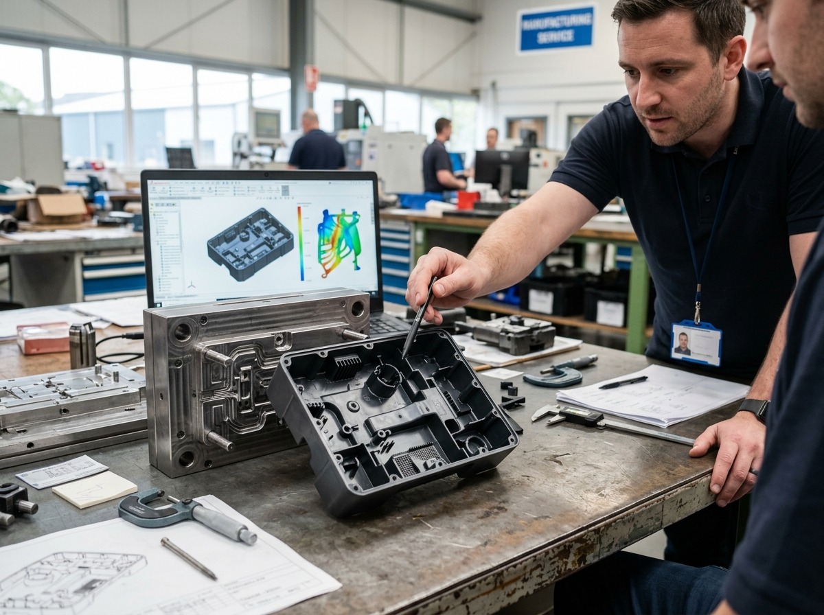
Complex parts usually fail at the interface between geometry, material behavior, and process control. A well-planned mold converts those risks into stable, repeatable production.
Outline
- Define the part requirements before cutting steel
- Use geometry rules that support filling and ejection
- Plan gate, cooling, and venting together
- Validate tolerances, shrinkage, and material limits
- Choose a supplier with matching product categories and project support
What Makes Complex Plastic Parts Difficult to Mold?
Complex plastic parts are difficult because thin walls, ribs, bosses, undercuts, and cosmetic surfaces compete for the same flow path. That combination increases the risk of uneven filling, trapped air, and dimensional drift.
For procurement teams and engineers, the real challenge is not only making the part, but making it consistently. ISO 20457 notes that molded plastics need tolerance evaluation different from metals, because processing and material behavior affect geometry in unique ways. ISO 20457 tolerance guidance helps frame that difference.
Start With Part Function, Not Mold Layout
Good custom plastic mold development begins with function, assembly, and appearance requirements. If the part must seal, snap, carry load, or match a visible surface, those needs should define the mold concept first.
Before detailing the tool, confirm the material, annual volume, cosmetic class, and critical dimensions. For a supplier overview, the homepage and core service pages at Plastic Metal Mold, professional injection moulding services, and plastic injection mold service show the main service scope and product categories.
Geometry Rules That Improve Injection Mold Design
Geometry is the fastest way to reduce risk in injection mold design. Uniform wall thickness, gradual transitions, and realistic draft angles lower stress, improve filling, and make ejection more stable.
Sharp internal corners should be avoided where possible, because they concentrate stress and often create sink or warp. Thick bosses should be cored out, ribs should be proportioned carefully, and cosmetic surfaces should avoid abrupt section changes.
Gate Placement
Gate placement controls how the cavity fills and where weld lines appear. A balanced gate location shortens flow length, reduces pressure loss, and helps keep the part dimensionally stable.
For complex housings, the gate should support both appearance and function. If the gate leaves a visible mark, place it on a hidden face or secondary surface when the design allows.
Cooling Layout
Cooling layout is often the main difference between a workable tool and a production tool. Uneven cooling creates differential shrinkage, which leads to warpage, twisting, and long cycle times.
ASTM D955 defines shrinkage measurement from mold cavity to molded dimensions for thermoplastics, which is why shrinkage data should be part of the design review. ASTM D955 shrinkage method is a useful reference when estimating cavity compensation.
Venting Strategy
Venting strategy prevents trapped gas from blocking the melt front. Without enough venting, the part may show burn marks, incomplete fill, or weak knit lines.
Vents should be placed at the last fill areas, around ribs, and near deep pockets. This is especially important for cosmetic enclosures and electronic housings, where trapped gas can damage surface quality.
| Design Area | Preferred Choice | Typical Benefit |
|---|---|---|
| Wall thickness | As uniform as possible | Lower sink and warp risk |
| Ribs and bosses | Cored and proportioned carefully | Better strength without heavy sections |
| Gate position | Balanced to flow and appearance | More stable filling and cleaner cosmetics |
| Cooling channels | Close to hot spots and thick zones | Shorter cycle time and less distortion |
| Vents | At end-of-fill and trapped-air zones | Fewer burns and short shots |
 Material Selection Changes the Mold Strategy
Material selection changes cavity sizing, venting, cooling, and ejection requirements. A resin with high shrinkage, high glass fill, or low flow will behave very differently from a general-purpose material.
For electronics and appliance parts, flammability and compliance may also matter. UL 94 covers flammability tests for polymeric materials used in devices and appliances, and the current standard edition is active. UL 94 standard is commonly referenced in product qualification.
For food-contact applications, the design team should also verify regulatory suitability. FDA maintains guidance and inventories for food-contact substances, and recycled plastic use is evaluated case by case. FDA food-contact packaging guidance is a useful starting point for those projects.
| Part Type | Main Design Priority | Common Risk |
|---|---|---|
| Electronics housing | Fit, appearance, and assembly | Warp, sink, and visible flow marks |
| Storage box | Wall balance and repeatability | Dimensional drift at corners |
| Food-contact cup | Material compliance and hygiene | Surface defects and contamination risk |
| Decorative sphere | Roundness and surface finish | Parting-line visibility |
| Shoe component | Wear resistance and structural stability | Uneven fill and deformation |
How to Reduce Trial-and-Error During Mold Development
Trial-and-error becomes expensive when the design review is incomplete. The best way to reduce it is to align part data, mold flow thinking, and process assumptions before tooling starts.
A practical workflow is to confirm the drawing, review the moldability, estimate shrinkage, define the critical dimensions, and then run the first trial with a clear inspection plan. According to industry estimates, many delayed projects are caused by late changes to wall thickness, undercuts, or cosmetic requirements.
- Freeze the part function and appearance targets first.
- Check draft, ribs, bosses, and undercuts for moldability.
- Set cavity compensation using material shrinkage data.
- Plan cooling and venting around hot spots and end-of-fill zones.
- Prepare trial criteria for size, appearance, ejection, and assembly.
Where a One-Stop Supplier Adds Value
A one-stop supplier adds value when design, tooling, trial, and production need to stay synchronized. That is especially useful for OEM and ODM projects, where schedule changes can quickly affect launch timing.
The target website’s main categories include plastic injection molds, plastic case molds, PC case molds, 3D molds, and custom plastic parts. Those categories are relevant because they cover electronics housings, complex curved parts, and general custom molding needs.
For buyers comparing suppliers, the most useful internal references are featured products, plastic products mould, and one-stop moulding injection service. These pages help map product categories to project types without relying on broad claims.
Supplier Directory: How to Evaluate Options
Supplier selection should be based on project fit, not only on price. For complex parts, the best suppliers are those that can support engineering communication, trial feedback, and repeatable mass production.
Well-known industry references for process and standards include ISO, ASTM International, UL Standards, and FDA. For manufacturing execution, established mold makers and injection molding suppliers should be compared on design support, tolerance control, and response speed.
- Check whether the supplier can handle drawings, samples, and concept development.
- Ask how they manage shrinkage, venting, and cooling in complex cavities.
- Confirm whether they support trial reports and modification feedback.
- Review whether they can move from prototype to volume production.
Conclusion
The best mold design for complex plastic parts is the one that balances geometry, material behavior, and production reality. When those three factors are aligned early, the result is fewer defects, faster trials, and more stable output.
For teams sourcing a custom plastic mold, the strongest decision framework is simple: define the function, design for flow, validate shrinkage, and choose a supplier that can support the full development cycle. That approach is more reliable than fixing problems after steel is cut.
FAQ
What is the most important rule in injection mold design for complex parts? The most important rule is to design for manufacturability before focusing on tooling details. Uniform wall thickness, realistic draft, and controlled flow paths usually prevent more defects than any later correction. This is especially true for visible housings and functional assemblies.
How do I reduce warpage in a custom plastic mold? Warpage is usually reduced by balancing wall thickness, improving cooling symmetry, and placing gates so the cavity fills evenly. Material shrinkage data should also be reviewed early. ASTM D955 is a useful reference when estimating cavity compensation and dimensional change.
Why does venting matter so much in plastic parts? Venting matters because trapped air can stop the melt front and create burns, short shots, or weak weld lines. Complex parts with ribs, pockets, or deep cavities are especially sensitive. Proper vent placement is a low-cost way to protect appearance and function.
When should a project use a 3D mold instead of a standard layout? A 3D mold is usually preferred when the part has complex curves, deep features, or detailed surfaces that are hard to form with a simpler cavity layout. It is often used for appearance parts and functional components that need more geometric precision.
What should buyers ask a supplier before starting tooling? Buyers should ask about design review, trial process, shrinkage control, modification support, and production ramp-up. They should also confirm whether the supplier can handle the target material and part category. Clear answers at the start reduce delay and rework later.
Post time: Jun-22-2026