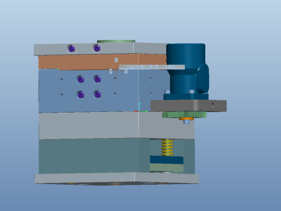
The design of mold drawings needs to comprehensively consider multiple key factors to ensure the structural rationality, processing feasibility and service life of the mold. The following is a summary of the core design elements:
1. Material selection and performance
Mold material
Select materials according to the mold type (injection molding, stamping, rotary cutting, etc.). For example, CR12 and CR12MOV steel (hardness 58-63HRC) are commonly used for injection molds, and cemented carbide or aluminum alloy may be used for stamping molds2.
The material must meet the requirements of strength, wear resistance, thermal conductivity, etc. For example, thermosetting plastic molds require high temperature resistant materials.
Material shrinkage
The injection mold needs to adjust the cavity size according to the plastic shrinkage rate. For example, the shrinkage rate of PC materials needs to be scaled separately.
2. Key points of structural design
Parting surface and mold opening direction
The parting surface should be selected at the maximum projected area of the product to avoid appearance defects.
The mold opening direction must be consistent with the demolding direction of the product to reduce core pulling or slider mechanisms.
Gating system and cooling system
The gate position needs to optimize the melt flow and shorten the flow length to reduce pressure loss.
The cooling water channel should be close to the heat load area of the cavity. Beryllium copper inserts or heat sink pins can be used to assist in heat dissipation.
Demolding and ejection design
Ejection angle: smooth surface ≥0.5°, rough leather grain ≥3°, avoid top injury or hair pulling.
The ejection force needs to be balanced. Too small will cause burrs, and too large will accelerate wear.
III. Processing technology and manufacturing feasibility
Processing method
Preferably use CNC machining (high precision), EDM (complex cavity) or wire cutting (slender structure).
Insert and splicing design
Complex structures (such as ribs and holes) need to be designed with inserts to avoid electrical machining.
Machining allowances need to be reserved at the splicing to ensure assembly accuracy.
IV. Tolerance and precision control
Dimension tolerance
Refer to national standards (such as GB/T14486-93), combined with material shrinkage and process capabilities.
Key structural tolerances
Slider clearance: 0.05-0.10mm on one side; the guide rail angle should avoid sharp corners, and the straight line segment should be ≥2mm.
5. Special process and functional requirements
Two-color/multi-material mold
The parting surface needs to maintain the consistency of the rear mold core, and the glue feeding point needs to avoid rotation interference.
Wear-resistant and maintenance design
High wear areas (such as trimming punches) need to be hardened, and the ejector force needs to be moderate to extend the life.
6. Drawing specifications and annotations
Views and annotations
Includes dynamic/fixed mold schematics, assembly drawings, cooling water channel axonometric drawings, annotated push rod lists and material lists.
Process requirements
Specify heat treatment parameters (such as quenching temperature), surface treatment (polishing, nitriding) and assembly sequence.
Summary
Mold drawing design needs to balance functionality, economy and manufacturability, and optimize the structure in combination with specific application scenarios (such as mass production, material properties)
Post time: Jul-11-2025

