
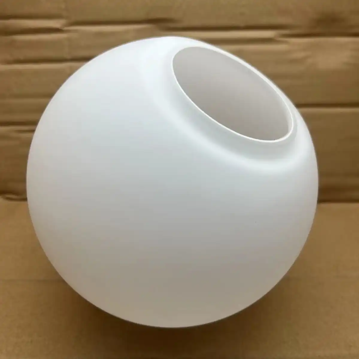
PC lampshade production process
Lampshades are very common products in daily life. The materials used for PC lampshades are basically diffused PC materials /PMMA materials. We can make both of these two materials. We have over 17 years of experience in mold making and have more than 100 cases of lampshade production. The following is the production process of lampshades
1. Demand analysis and digital design
Optical performance modeling
Light simulation: Use LightTools or Zemax OpticStudio to establish the light path model to ensure that the light transmittance of the lampshade is ≥92% (characteristics of PC material) and avoid glare (UGR<19);
Structural verification: Utilize ANSYS topology to optimize the mold wall thickness (conventional 1.5-3mm), balancing lightweight and impact resistance (capable of withstanding a 3kg drop ball impact).
3D design of molds
Typing strategy: For complex surfaces (such as Fresnel patterns), asymmetric typing lines are adopted, combined with a three-dimensional slider connecting rod mechanism (angular tolerance ±0.01°);
Conformal cooling: Metal 3D printed titanium alloy water channels (diameter 1.2-2mm) ensure that the temperature fluctuation of the mold is ≤±1.5℃, preventing stress whitening of PC material.
2. Precision machining and surface treatment
Core technology:
Cavity milling, five-axis ultra-precision machine (GF Machining Solutions), surface roughness Ra≤0.02μm
Microstructure etching, femtosecond laser + nanoimprint composite process, Fresnel depth 0.05mm±0.003mm
Electrode processing, electrical discharge machining of graphite electrodes (discharge gap 0.03mm), edge R Angle ≤0.1mm
Surface strengthening treatment
Optical-grade polishing: Multi-stage polishing with diamond gypsum (from W40 to W0.5), combined with magnetorheological polishing (MRF) to eliminate sub-surface damage;
Anti-sticking coating: Diamond-like carbon (DLC) coating (with a thickness of 2-3μm) reduces the demolding force to <5kN and extends the mold life to 800,000 molds
3. Mold trial verification and mass production optimization
Injection molding process window
Temperature control: Barrel temperature 280-310℃ (PC melt index 18g/10min), mold temperature 90-110℃ (to prevent cold material scratches);
Pressure curve: Three-stage pressure holding (60MPa→45MPa→30MPa), compensation shrinkage rate 0.6-0.8%.
Defect closed-loop correction
The weld line is developed and the gate position is unreasonable, resulting in the convergence of multiple flows. Adjust the timing of the hot runner valve needle (error ±5ms)
Spot deformation, microstructure collapse of the mold or uneven polishing, local repair welding + ion beam shaping (correction amount 0.005mm)
Stress cracking, insufficient demolding slope (<1°) or too fast demolding speed, increase the number of demolding pins (1 per 100cm²)
4. Key points of injection mold production:
Optical performance and structural design
Light transmittance and optical path control
Surface microstructure: Nanoscale Fresnel lens design (depth accuracy ±0.003mm), achieved through laser etching or electroplating processes, with a light scattering Angle of ≤15° and avoiding glare (UGR value needs to be <16);
Wall thickness uniformity: The topological optimization algorithm (ANSYS Discovery) is adopted to balance the light transmittance and intensity. The wall thickness is 1.2-2.5mm, and the tolerance is controlled within ±0.05mm. Parting lines and demolding strategies
Asymmetric parting: For irregular curved surfaces (such as petal-shaped lampshades), 3D sliders and hydraulic core-pulling connecting rods are adopted. The parting line offset Angle is ≤0.5° to ensure no flash.
Demolding slope: The slope of the optical surface ≥1.5°, and the slope of the non-optical surface ≥0.8°. The ejection system adopts silicon nitride ceramic ejection pins (friction coefficient <0.1).
The collaborative optimization of materials and process
Selection of mold steel
High-polished steel: S136 SUPREME (HRC 52-54) or German Gritz 1.2085 ESR (mirror-polished to Ra 0.008μm) is preferred;
Corrosion-resistant treatment: The surface is coated with a diamond-like carbon (DLC) layer (2-3μm thick), which can resist the acidic gases produced by the high-temperature decomposition of PC.
If you want to customize a similar PC lampshade, you can come to us. We can share many cases we have made, allowing you to see our quality and experience our service
Post time: May-16-2025